Last update=16 May, 2006


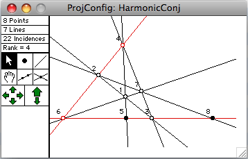
Above is a typical projective configuration window containing the harmonic conjugates construction. Points and lines are stored as real homogeneous coordinates. The projective plane is modelled as half the surface of a sphere, projected onto a tangent plane. Some of the algorithms used are described in W. Kocay and D. Tiessen, "Some Algorithms for the Computer Display of Geometric Constructions in the Real Projective Plane", Journal of Combinatorial Mathematics and Combinatorial Computing 19 (1995), 171-191; and in W. Kocay and R. Szypowski, "The Application of Determining Sets to Projective Configurations", Ars Combinatoria 53 (1999), 123-145.
- The arrow tool is for selecting and moving points and lines.
- The bullet tool is used for adding new points to the diagram. Hold the option key to constrain the new point to be incident with an existing line.
- The line tool is used for adding new lines to the diagram. Hold the option key to constrain the new line to be incident with an existing point.
- The join tool creates lines connecting all pairs of selected points.
- The intersect tool creates points at the intersection of all pairs of selected lines.
- The panning arrows allow the diagram to be panned left/ right/ up/ down.
- The zoom arrows zoom the drawing.

Projective Plane Functions Available in G&G 3.0
Incidence Graph
Construct the bipartite incidence graph of points versus lines. Option-clicking in either window will show the corresponding object in the other window. Given a 2-connected, bipartite graph X with girth at least 6, G&G will view X as the incidence graph of a projective configuration, and attempt to convert it to a drawing in the plane.Determining Set
A determining set is a minimal set D of independent points and/or lines such that if coordinates are assigned to the objects of D, then the coordinates of all points and lines in the configuration are thereby determined. G&G uses determining sets for animating projective configurations. Given a selected point or line P, this item will cause G&G to find a determining set containing P. If the configuration has an incidence graph, it will also construct a digraph hiliting the determining set and the "construction sequence", which shows the order in which the points and lines were determined.Dual Drawing
Interchanging the roles of points and lines results in a dual drawing in another projective plane window. Option-clicking in either window will show the corresponding object in the other window.Immobilize/Mobilize
Clicking and dragging an object will cause most points and lines in the drawing to move. Most drawings will animate much more smoothly if several points or lines are immobilized. This is because it limits the degrees of freedom of the configuration, thereby forcing a simpler kind of movement. Immobilized points or lines can be allowed to move again by mobilizing them.Force Incidence
Some drawings can only be constructed with the correct incidences if the points and lines have special values of their coordinates. Given a selected point P and line L, G&G attempts to adjust the coordinates to make P and L incident in the drawing. If it succeeds, the diagram will become more restricted in its motion. Some diagrams will become rigid. Some diagrams will collapse if there is no coordinatization with this incidence.Remove Incidence
Remove an incidence between a point P and line L, to allow more flexibility in a diagram which is rigid. When the diagram is then animated the point and line will tend to drift apart.Send to Infinity
The projective plane contains points at infinity that are no different from other points in the plane. G&G can send a point or line to infinity. Unless it is an immobilized object, it will tend to drift away from infinity as soon as the diagram is animated.Convert Graph to Projective Drawing
Given a connected bipartite graph with girth at least 6, G&G will view it as the incidence graph of a projective configuration, and attempt to draw it as a projective configuration. This is always possible if the degree of every vertex is at most 3. Sometimes it may be necessary to represent a line as a circle, as in the drawing of the Fano configuration, or other configurations.
 Back to the Groups & Graphs home page.